Electrical Rating
Brush up on conversion basics, familiarize yourself with switch terms and acronyms, and discover more about lamps and LEDs, processing and electrical ratings, and materials associated with the NKK product line.
RERATING CURRENT FOR SWITCHES WITH 125V AC ORIGINAL RATINGS
Generally, most switch applications can be classified into one of the below load categories. Switch capacities can be mathematically rerated when the application calls for a category or voltage other than the switch standard general specification ratings, meaning original current ratings at 125V AC. NKK has not conducted life tests at these rerated voltages and currents so it is important to contact the factory in such cases. The candidate switch should be tested in the actual application in which it is intended to function.
FOR CALCULATING RERATED CURRENT AT VARIOUS LOADS
| New Voltage Rating |
Resistive Load Multiply by: |
Inductive Load Multiply by: |
Lamp Load Multiply by: |
Motor Load Multiply by: |
Capacitive Load Multiply by: |
|---|---|---|---|---|---|
| 125VAC | 1 | 0.66 | 0.25 | 0.33 | 0.25 |
| 250VAC | 0.66 | 0.33 | 0.16 | 0.22 | 0.16 |
| 12VDC | 1.25 | 1 | 0.31 | 0.41 | 0.31 |
| 30VDC | 1 | 0.5 | 0.25 | 0.33 | 0.25 |
| 48VDC | 0.33 | 0.25 | 0.08 | 0.11 | 0.08 |
| 125VDC | 0.05 | 0.03 | N/A | N/A | N/A |
| Sample Calculation for model M2012SS1W01 | Sample Calculation for model JWL22RCA | ||||
| with 6A @ 125VAC resistive rating. To use at 48V inductive, multiply 6A x 0.25 = 1.5A @ 48VDC |
with 16A @ 125/250VAC resistive rating. To use at 30V DC motor load, multiply 16A x 0.33 = 5.28A @ 30VDC |
||||
Resistive Load
Resistive loads can be purely resistive or of the tungsten-heater load type. A resistive load that has no heating element is the easiest for a switch to handle, and the switch's rating is based on this type of load. A resistive load is one in which 100% of the load is composed of resistive devices. The power factor is high (PF =1) and contact erosion is low. Consequently, the switch's electrical life can be anticipated with some certainty.
Lamp Load
When a switch closes on a resistive lamp load, the switch sees a short circuit because the cold resistance of the lamp filament is near zero. The surge current as the switch closes can be many times the steady state current. As the lamp filament heats up to operating temperature, the resistance of the filament increases and the current decreases to the lamp's steady state.
Motor
Motor loads present yet another brutal environment for switch contacts. Closing the switch contact on a motor start-up load causes very large current surges of about 3 to 8 times the running current. When the switch is opened and the current decreases, the magnetic field of the inductor collapses and an electromotive force is induced. The polarity of the induced voltage is such as to oppose any change in current flow. This induced voltage aids the source voltage in striking an arc and maintaining it as the contacts separate.
Inductive Load
Non-motor inductive loads, such as those seen in switching power supplies, have inrush currents that greatly exceed the normal operating currents of the equipment. This inrush current can easily reach 8 to 10 times the steady state current. As a switch on an inductive load is opened, the inductor, or transformer, inducesa counter option "voltage" in the circuit. This voltage opposes any change in the circuit current and can reach hundreds of volts. This extremely high voltage can restrike the arc as the switch contacts open resulting in severely eroded or welded contacts.
Capacitive
With such loads as DC power supplies, welding machines, and strobe charging units the inrush current is even more damaging than with inductive loads. To the switch a capacitive load appears as a dead short as the switch closes. In the first few milliseconds the inrush current can sometimes reach 100 times the steadystate current of the circuit. Even worse for the switch, this inrush occurs before the contact bounce has subsided. This produces severe arcing and massive contacterosion. Often the contacts weld upon closure preventing the switch from ever opening. In an emergency the operator of the equipment would know he could not open the circuit.
INDUCTIVE DC LOADS
In AC circuits the voltage and current are varying in a sinusoidal pattern; both the voltage and current cross the zero reference 120 times per second for 60Hz. Therefore, the chances of closing or opening a switch when the voltage and current are at their maximum in AC circuits is remote.
In DC circuits the voltage and current do not vary and are always at their rated levels. Compared to AC circuits with the same voltage and current, DC circuits handle 1.414 times the power. Therefore, when opening or closing a switch on a DC load, the arc developed is more severe, more energetic, and lasts longer causing more contact erosion and a shorter switch life. A switch intended for a DC circuit should have its AC capacity rerated for DC. See previous page for rerating current.
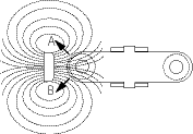
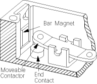
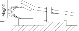
DESIGN FOR INDUCTIVE DC LOAD MODELS S800 & SW3800
Bar magnets are placed at each end of high capacity switches, and their magnetic field opposes the field created by the arcing current, thereby extinguishing the arc and protecting the contacts. Positive (+) must be connected to end terminals and negative (-) to common terminals.
TV RATINGS
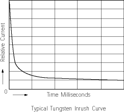
The TV5 and TV8 ratings are tested and assigned by the Underwriters Laboratory. The switches are intended to be used as "Power ON" devices in equipment where a high tungsten inrush current is anticipated, such as tungsten-filament lamp loads or entertainment equipment like sound systems and monitors.
An example is the TV8 test which consists of an overload test and an endurance test. The overload test consists of a switch closing on a minimum inrush current of163 amps with 50 consecutive operations at a rate of 10 cycles per minute. The test must be conducted without any failures. In the endurance test the current is reduced to 117 amps, and the same switch is subjected to another 25,000 operations.
The JWL is a product example that has been tested and meets the TV8 rating. In addition to the electrical testing, the switch enclosure (housing) must comply with the requirements for classifying materials as UL94V-0. The insulation material must have arc-tracking characteristics with a minimum arcing time of 180 seconds when tested in accordance with the Standard Test Methods for High-Voltage, Low-Current Arc Resistance of Solid Electrical Insulation. The JWM and JWL switches are rugged, dependable, and well suited to high inrush circuits.
OPERATING RANGE
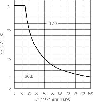
Three contact materials are commonly used in NKK switches: gold, silver, and gold over silver. These materials give the options of low level, power level, plus combined power and low level ratings.
Low Level ~ 0.4VA maximum @ 28V AC or DC maximum
Gold plated contacts are recommended for dry circuits, which are defined as very low energy. In circuits where the voltage is below 28 volts DC and current is below 100 milliamps (dry circuits), no arc develops as the contacts open or close. So, the tarnish remains. Eventually without the arc, the contacts become so encrusted that the switch is unable to close the circuit due to the high contact resistance. The solution to this is plating the silver contacts with gold, which does not tarnish. Gold plated contacts close under low voltage and low current conditions indefinitely, or for the mechanical life of the switch.
Power Level ~ 100mA to 10 amps @ 125V AC
Silver contacts are recommended for electrical levels above 0.4VA. Although silver tarnishes, it is a good conductor and this electrical energy is sufficient to break through the tarnish to give reliable performance. The oxidation which coats the contact surfaces with a hard layer of insulative contamination is removed by arcing. In circuits where the voltage is above about 12 volts DC and the current above .5 amps, an arc develops during opening or closing of the contacts. This arc keepsthe oxidation cleaned off.
Power or Low Level
Gold over silver contacts are used in applications requiring both dry and power circuits. NKK's gold over silver contacts have dual ratings as further described below.
DUAL RATINGS
The dual rated option is suitable where identical switches are used in both a logic and a power level circuit within the same application. Dual rated switches enable the user to install the same switch in both a logic level (dry circuit) and a power level circuit. However, once a code "A" rated contact switch has been used at a power level, it cannot then be used at a logic level. There may be advantages to stocking only a single switch for use in both a logic level and a power level circuit. Our dual rated contact material option allows this advantage. However, once a dual rated contact material switch has been used at a power level it cannot then be used at a logic level. The gold over silver contact material provides a reliable, tarnish free, contact surface for logic level switching. When this same contactmaterial switch is used in power level circuit, the gold plating is removed by contact arcing. If an attempt is then made to use this sameswitch in a logic level circuit (where no arcing occurs). The low current condition cannot provide adequate contact wiping or cleaning.

