Fundamentals of Switches: Series 2
The protection provided by the switch against ingress of dust and water is rated under the IEC standard. The rating is shown as IPxx, where xx is a two-digit number. The first digit denotes the level of dust protection.
31. Water and dust proof rating---part 1
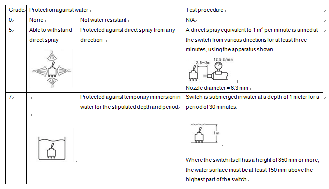
The protection provided by the switch against ingress of dust and water is rated under the IEC standard. The rating is shown as IPxx, where xx is a two-digit number. The first digit denotes the level of dust protection. For most switches this will be 6, meaning that the switch is fully protected against dust and particles. The second digit will normally be one of 0, 4, 5 or 7, where 0 signifies no water resistance, 4 means waterproof for splashes only, 5 means waterproof for direct spray, and 7 means that the switch can be submerged to a depth of 1 meter for 30 minutes without damage (provided that the switch is not operated while underwater). Typical IEC ratings for switches are IP64, IP65 and IP67. Thus, an IP67 switch is 100% dustproof and also waterproof to a depth of 1 meter for 30 minutes.


32. Water and dust proof rating---part 2
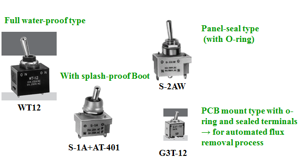
A rating such as IP67 may be limited to specific internal sections of the switch. Where the switch is mounted on a panel, for example, the dust and water resistance of the panel applies to the front face only, and is denoted “panel seal IP67” or equivalent. Conversely, in some cases the entire switch will be rated IP67. Switches in the WT, WR and WP series, for example, include lead wires and are rated IP67 100% waterproof.
33. Water and dust proof rating---part 3
Bushing type toggle switches and pushbutton switches may be fitted with waterproof caps to protect against water and dust. These are usually made of rubber and are designed to cover the switch control and lock nut in order to prevent damage to the rear of the panel.
34. Water and dust proof rating---part 4
Some switches are able to withstand a direct water spray. These are typically designed for short automated solder flux washing processes and provide only a base level of water resistance. As such, they do not have IP waterproof ratings.

35. Current rating and load---part 1
The switch rating denotes the maximum load capacity in terms of current and voltage for example, AC 125V 6A---and serves as a key indicator of the overall performance of the switch. It is important to remember that the ratings are based on best-case load conditions with the switch connected to resistive load.
36. Current rating and load---part 2
Resistive load is where the switch is connected to resistance only. In reality, there is no such thing as a circuit with pure resistive load; all circuits, even those considered to be pure resistive load, contain inductive and/or capacitive components in some form. For this reason, the actual current should be no greater than 80% of the rated current.
37. Current rating and load---part 3
Other than resistive load, the main load types are inductive load, lamp load, motor load, condenser load and DC load.

38. Current rating and load---part 4
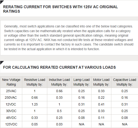
Inductive load is present in circuits comprising coil elements such as a motor, transformer or solenoid. When the circuit is broken, a large reverse induced voltage is generated, with the potential to produce arcs that cause wear on the switch contacts. As a general rule, for a switch rated at AC 125V with a power factor of 0.6, the current capacity should be no greater than 1/2 to 1/3 of the resistive load.
39. Current rating and load---part 5
Lamp load, as the name suggests, occurs when the circuit contains a lamp (i.e., an incandescent light bulb). If the lamp filament is cold when the switch is turned on, a transient current of about 10 - 15 times the normal current may be generated. In extreme cases this can melt and even fuse the contacts. As a general rule, the current capacity for lamp load should be no greater than 1/4 - 1/5 of the resistive load.
40. Current rating and load---part 6
Starting up a motor generates an instantaneous current, called inrush current, when the circuit is closed. The inrush current is of the order of 3 - 8 times the normal current. This can cause significant wear on the contacts. The magnitude of the inrush current depends on the type of motor. The current capacity for motor load should be no greater than 1/3 of the resistive load.
41. Current rating and load---part 7
Condensers generate an even larger inrush current, by absorbing and then releasing current when the switch is turned on. The inrush current should not exceed the rated current. The inrush current should be measured in the actual circuit.
42. Current rating and load---part 8
Unlike alternating current (AC), direct current (DC) does not reach zero voltage or current at any point. This means that large arcs may be generated even in low-load situations. At 50V or more, the arc can last for a significant period of time, preventing the circuit from being switched off. At DC 125V, the current capacity should be no greater than 1/20 of the resistive load at AC 125V, or 1/30 - 1/40 of the induction load (where power factor = 0.6).
43. Current rating and load---part 9
The choice of switch will depend on the type of circuit and the operating conditions. Be sure to allow a margin for error.

